Fractures (part 1)

As part of an expanding laboratory, EDT’s Kansas City District Office has added a Scanning Electron Microscope (SEM).
Our SEM is capable of 100,000X magnification, allowing a close-up look at material surfaces for defects, inclusions, and fracture characteristics. In addition, the SEM includes Energy Dispersive Spectroscopy (EDS) which uses x-ray technology to determine material composition (atomic elements). In effect, you can zoom in on very small areas and see what’s there and determine the type of material used in making the part.
By using a SEM/EDS to study the surface of the fracture, the question of how the part broke - or the mode of fracture - can be answered. Was the part pulled apart, sheared, twisted or bent? Once this is established, a review of the history of the breakage or failure may assist in answering the questions: Why did it break? or What was the cause?
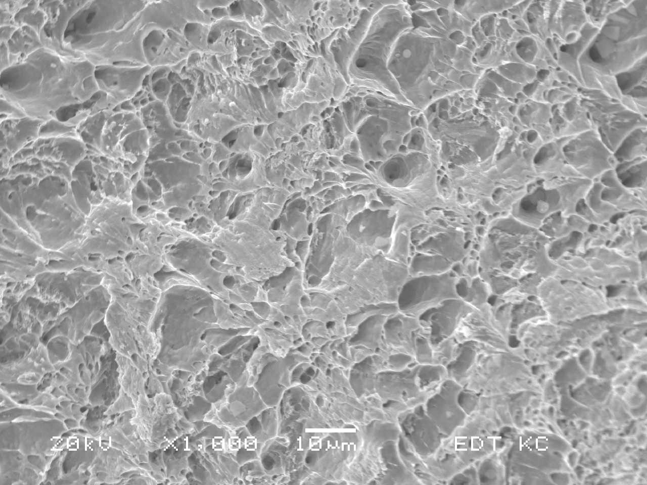
The four principle fracture modes are: dimple rupture, cleavage, fatigue, and decohesive rupture. Dimple rupture is caused by a common process known as microvoid coalescence. As the part is being pulled apart, the ductile material (think salt water taffy) creates tiny bubbles (microvoid coalescence) in the material. When the part fractures into two sections the tiny bubbles break leaving cuplike depressions. The cuplike depressions are referred to as dimples. As such, dimple ruptures are most often associated with ductile fractures.
Cleavage is a low-energy type of fracture that displays matched faces, flat and featureless surfaces that are most often associated with brittle breaks. The best way to visualize this type of fracture mode is to think of a thick chocolate bar that is broken in half. The amount of energy and effort to break the chocolate bar is low (i.e., low energy) and the brittle fractures are smooth, flat, and look alike when compared to each other.
Fatigue fractures are associated with repetitive and/or cyclic loading. The best way to visualize this fracture mode is to bend a paperclip back and forth until it breaks. As the paperclip is bent back and forth, the paperclip is subjected to three stages. Stage I: the start of the break or crack initiation, Stage II: the growth of the break or crack propagation, and Stage III: the final breakage of the paperclip into two sections or catastrophic fracture.
Decohesive rupture is a fracture associated with a reactive environment (i.e., being subjected to hydrogen, sulfur, phosphorus, chlorides, etc.) and the fracture propagates along/across grain boundaries. In other words, the part breaks due to the corrosive environment in which it is used. The fracture occurs along the molecular grain boundaries of the material and requires high magnification to view.
With the addition of a JEOL JSM-6060LV Scanning Electron Microscope with Energy Dispersive Spectroscopy (SEM/EDS) in the EDT Kansas City District Office, a ductile fracture surface was examined to illustrate a dimple rupture fracture mode.
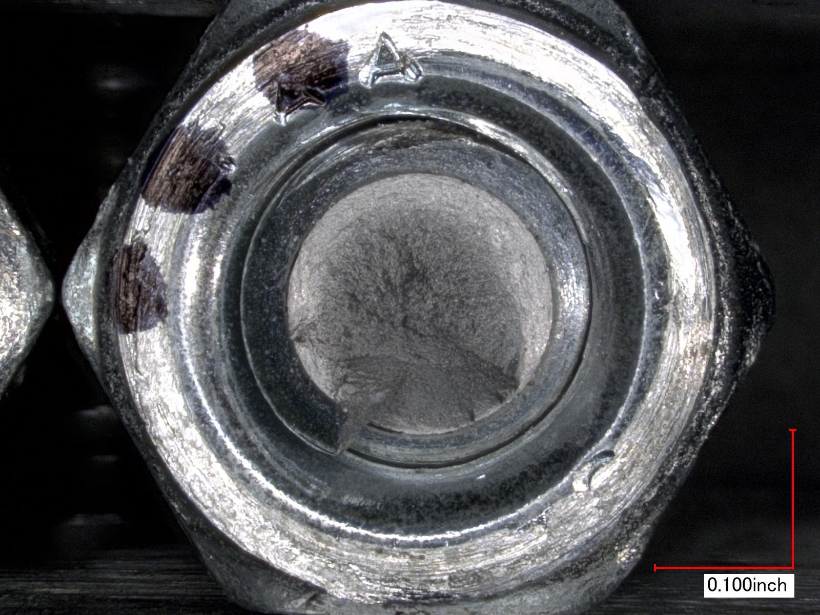
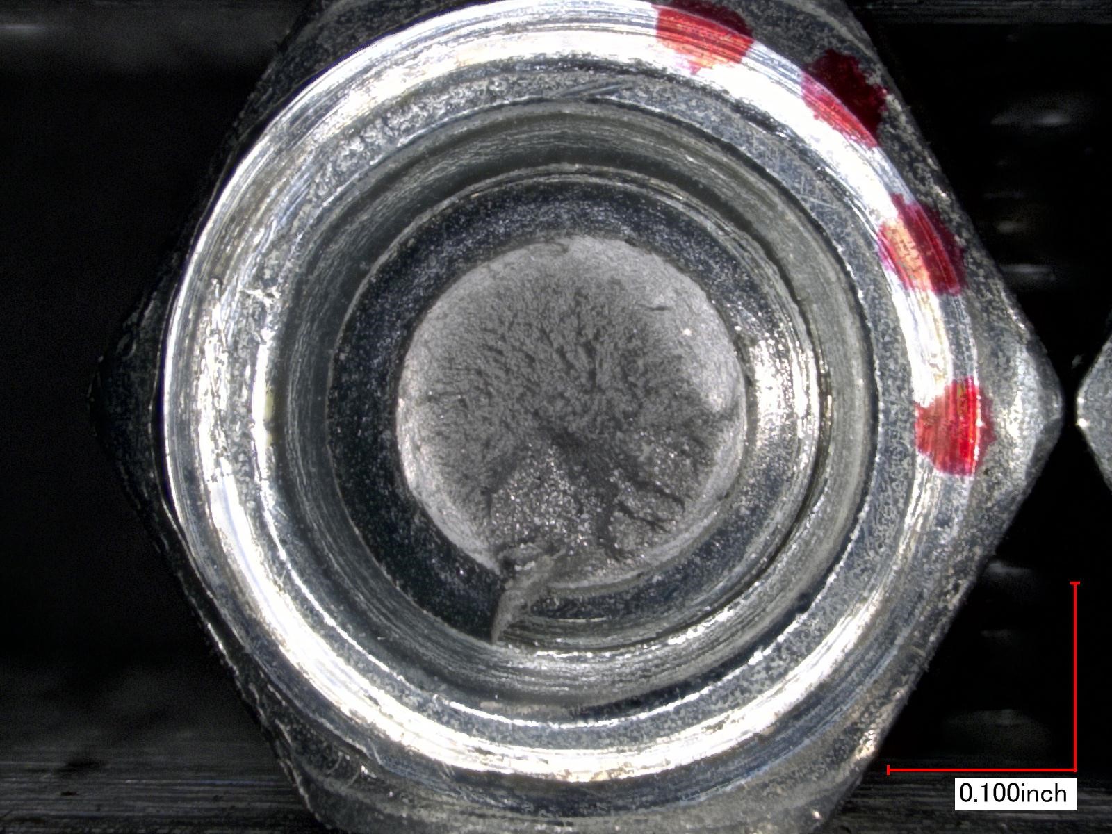
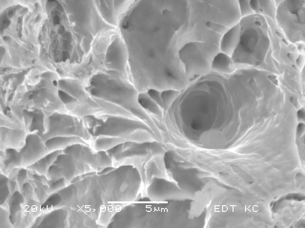
Standard 1/4-20 steel bolts were purchased and subjected to over-tightening to fracture at room temperature. The fractured bolt was placed in the SEM/EDS and the fracture surface was documented for mode of fracture. The fractured bolt at room temperature exhibited very small cuplike depressions, or microvoid coalescence, that are indicative of a dimple rupture fracture mode. SEM/EDS images of the dimple rupture are shown in Figures 1 and 2.
Faces of Dimple Rupture Fracture
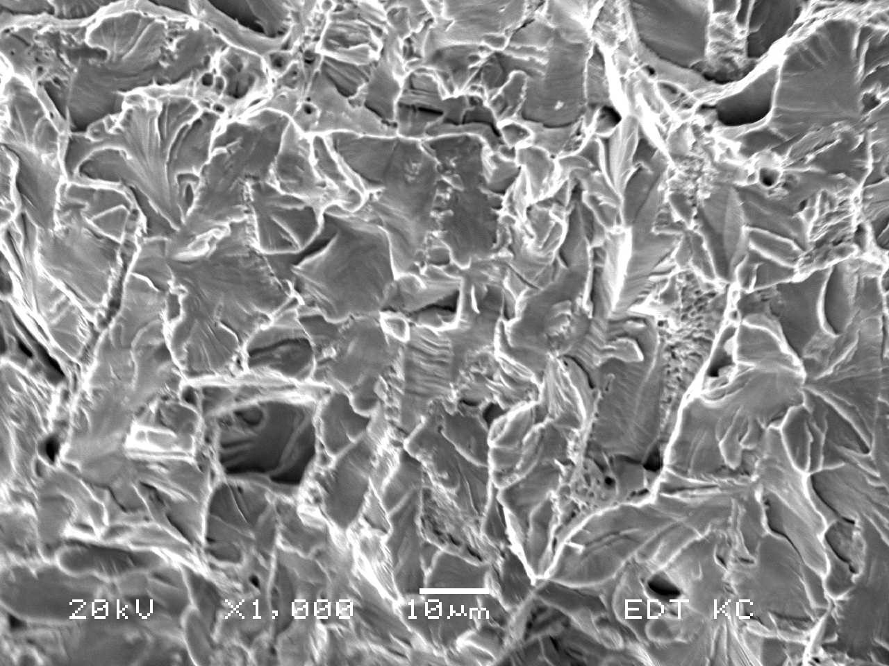
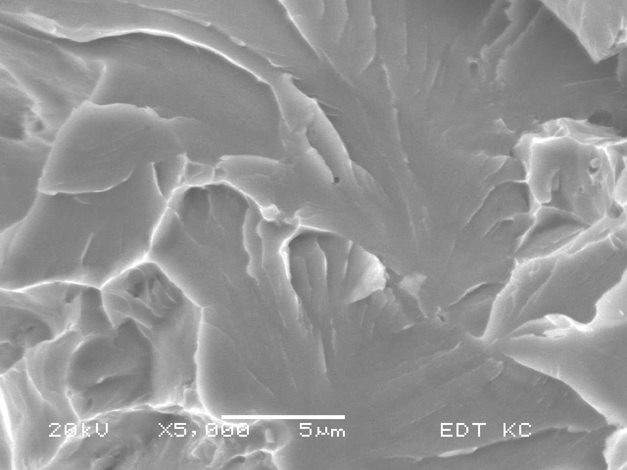
Next, a brittle fracture surface was examined to illustrate the fracture mode identified as cleavage. The same bolt types were subjected to over-tightening to fracture after cooling with liquid nitrogen at -321° F. The fractured bolt was placed in the SEM/EDS and the fracture surface was documented for mode of fracture. The liquid nitrogen-cooled bolt exhibited a cleavage fracture mode. SEM/EDS images of the cleavage fracture surface are shown in Figures 3 and 4.
Faces of the cleavage fracture
The two bolts were manufactured from the same material but exhibited different fracture modes. The only difference between the two bolts was the temperatures at which the fracture was induced. The dimple rupture fracture manifested at room temperature while the cleavage fracture developed after the bolt material was cooled to -321° F, where the material exhibited a brittle fracture mode due to the lowered temperature.
In part 2, we will discuss the importance of environmental fractures with regard to failure analysis, fatigue fractures and decohesive ruptures.
_____________________