Centrifugal Compressors – Simultaneously Simple and Complex

Centrifugal compressors (aka- turbocompressors) though you may not be familiar with them, we need not look far to find examples in our daily lives. They can be found on planes, trains and automobiles in various sizes and shapes. They are particularly popular on aircraft where they are used to do various jobs, among them pressurization of aircraft cabins as well as in air cycle machines, keeping occupants comfortable thanks to their compact size and simplicity (relative to other compressor types). Common examples on small aircraft, trains and automobiles include turbochargers, a device that combines a centrifugal compressor with a turbine on a common shaft, making use of otherwise wasted heat and energy from an engine’s exhaust, using it to drive a compressor to pump additional air into an engine, (aka-supercharging or in this case “turbocharging” which results in improved engine efficiency and power output). Beyond transportation, centrifugal compressors are often found in wastewater applications for aeration in various stages of the treatment process, HVAC applications where they are utilized to compress refrigerants as well as in the oil and gas industry and petrochemical plants where they are incorporated into various processes.
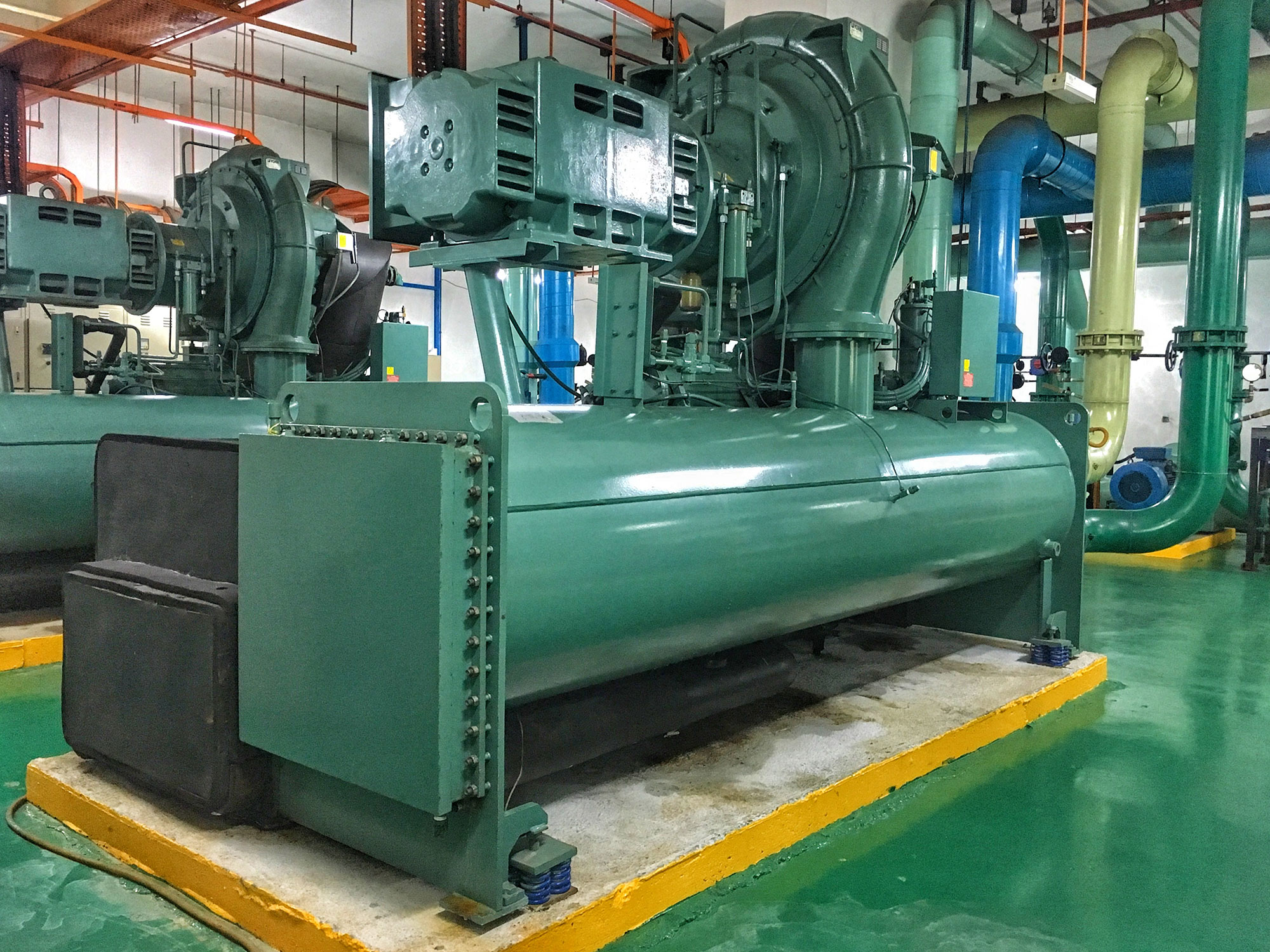
Figure 1 Large Centrifugal Compressor
While there are many types and configurations of compressors (rotary screw, axial, reciprocating to name a few), centrifugal compressors are favored for their relative simplicity as well as their ability to flow large volumes of working fluid (air, refrigerant, etc.) at moderate pressures. While it is not uncommon for single-stage air applications to top out at or near a 3:1 pressure ratio (the compressor triples the incoming pressure of the working fluid), specialized designs have been developed to operate at pressure ratios of 10:1 in a single stage, and do so in a compact package in comparison to compressors of other types having similar capacities.
As far as the name implies – centrifugal compressors operate in much the same manner as a centrifuge (as well as a playground merry-go-round) – where rotation is utilized to accelerate an item (or fluid in this case) from the center, expelling it toward the outside diameter (some of you may recall sitting in the middle of the merry-go-round trying to stay in the middle until it reached a point where you could no longer hang on..). In the case of a centrifugal compressor, the rotating member is an impeller – a specialized fan of sorts that utilizes a series of contoured blades to direct the incoming fluid (which is flowing directly into the face of the blades) and redirect it outward, perpendicular from the incoming direction, discharging the fluid into a diffuser and (in the case of a single stage compressor) into a snail-shaped member that is referred to as a volute, compressor housing or scroll.
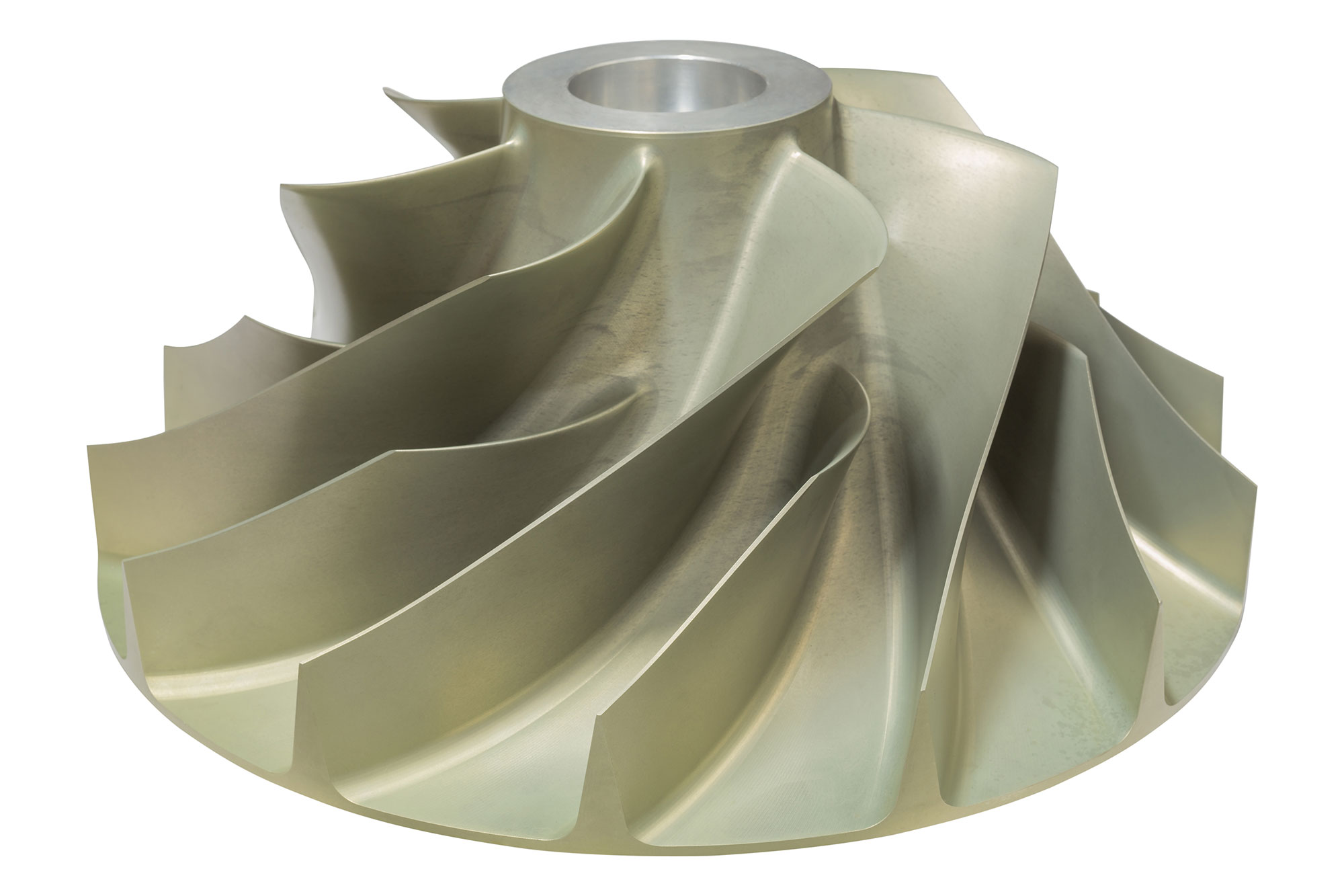
Figure 2 Centrifugal compressor unshrouded impeller
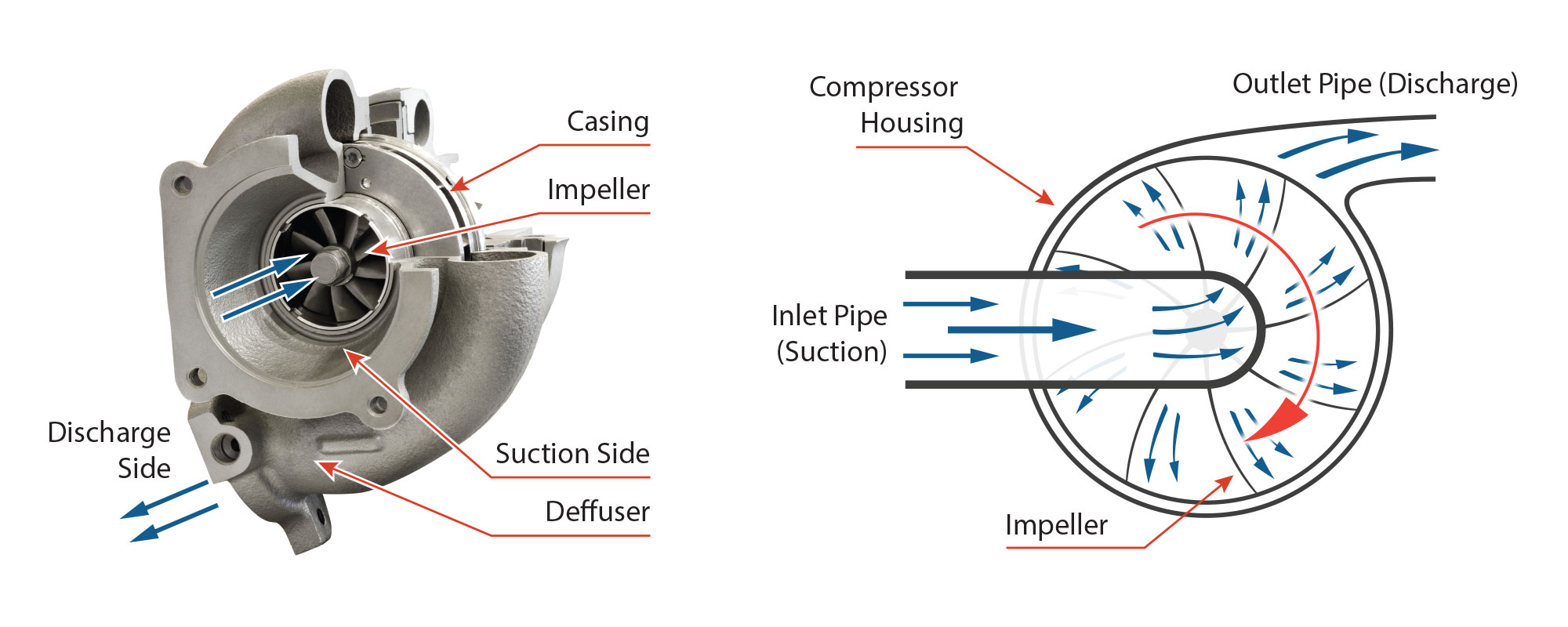
Figure 3 Centrifugal compressor illustration
While the impeller accelerates the fluid into the volute, the pressure continues to rise as the fluid slows down in the volute. Regarding impellers, there are a number of variables pertaining to blade geometry that may be manipulated by the designer to optimize the performance of a given compressor. Often manipulated variables include how many blades are used, the inner and outer diameter of the impeller blades and hub, whether or not tall (full) and short (aka splitter) blades are mixed (use of mixed blade heights often increases flow capability at the expense of efficiency at higher pressures), blade-to-volute clearance. Other more complex elements of blade design such as lean, backsweep (do they point straight outward or do they “sweep” backward at the impeller discharge), and twist (how many degrees difference is there between the inlet and discharge of the blade) can also be manipulated to modify the performance of the compressor. In general, the goal in impeller design is to guide/direct the air from the inlet to the discharge in the smoothest possible manner, avoiding rapid changes in fluid volume or velocity as it makes its way through the blades, as well as achieving the targeted flow rates and pressures. As far as impellers go, there are two primary types – shrouded and open (unshrouded). Unshrouded impellers leave the blades exposed where they are more subject to flex and oscillation, while shrouded impellers feature a shroud over the blades that ties them together – increasing blade stability at the expense of added weight and susceptibility to fouling by ingested dirt or debris that may cling to the interior surface of the shroud. In addition to diminished performance, fouling of a shrouded impeller can also result in increased vibration, thereby reducing reliability. That being the case, shrouded impellers tend to be found more on multi-stage applications where very clean/pure working fluids are utilized.
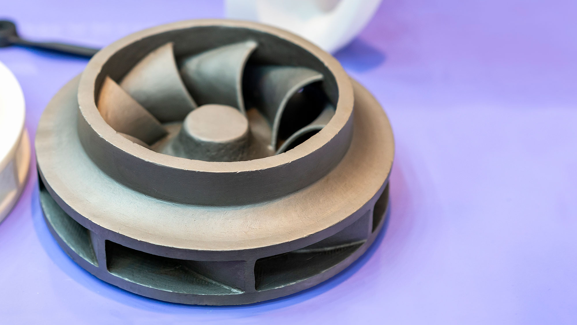
Figure 4 Shrouded impeller
In cases where higher pressures are demanded (refrigeration for example), multiple stages may be combined where the flow out of one impeller is directed into the impeller of a subsequent impeller. Used in this configuration permits the achievement of much higher pressures while retaining the efficiency and compactness centrifugal compressors are known for.
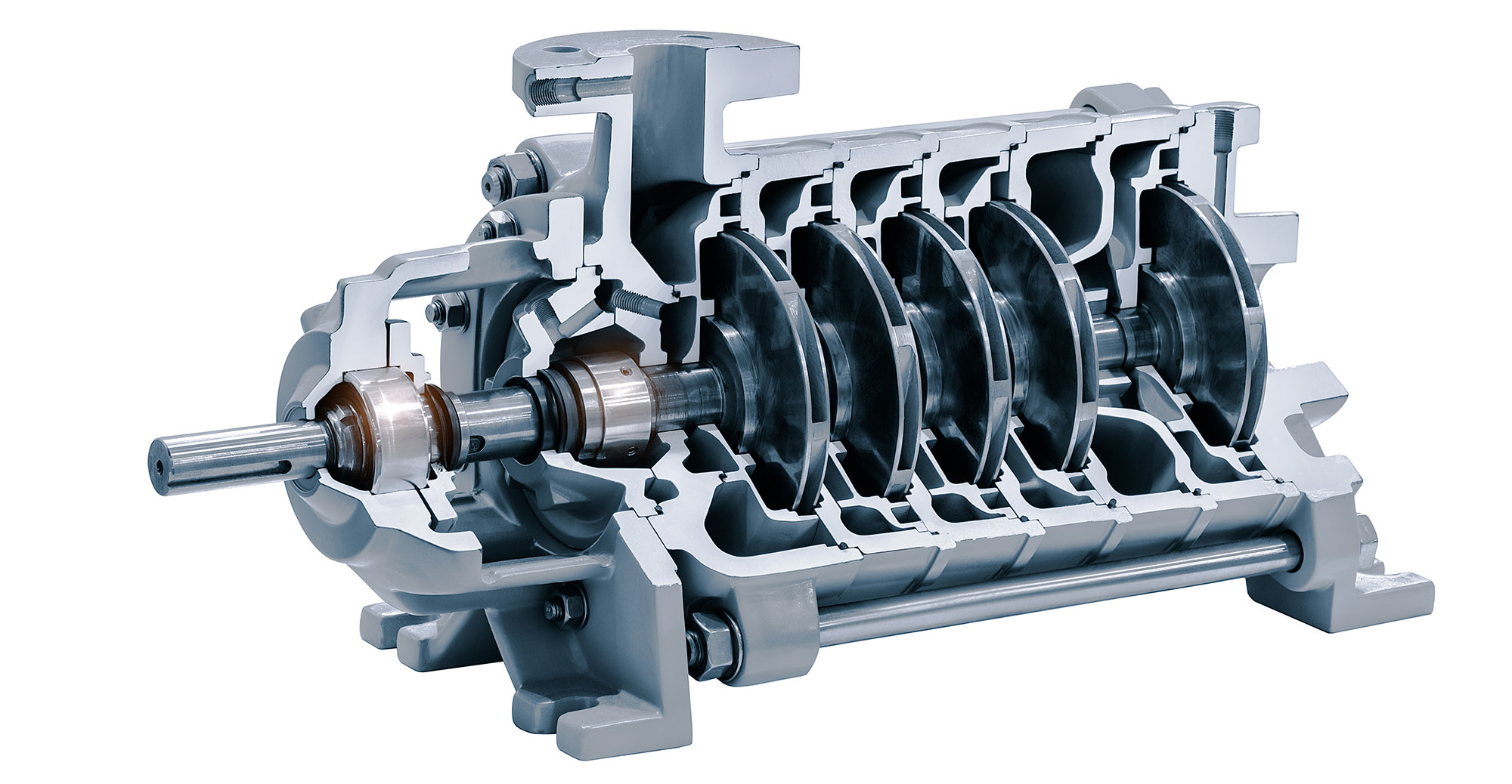
Figure 5 Multi-stage centrifugal compressor using shrouded impellers
One key feature that makes centrifugal compressors more desirable than other types of compressors is their efficiency. Since centrifugal compressors utilize a rotating impeller, operating in close proximity to the walls of the volute (clearances ranging 0.020” to 0.050” are common) at high speeds (impeller speeds exceeding 50,000 rpm are observed in many applications), fluid flow is continuous (as opposed to reciprocating compressors where air is pumped in and out of chambers in separate cycles) and there is no frictional contact between the impeller and the volute; in addition to efficiency gains resulting from continuous flow and the reduced friction between moving parts, there are also fewer moving parts to wear out. This being the case, centrifugal compressors can provide cost savings in the form of reduced energy consumption, reduced downtime and maintenance costs as well as savings associated with a reduced need for space. That said, since centrifugal compressors operate at such high rotational speeds, they often require high precision gears and bearings which can drive up the initial cost relative to other compressor types. The other primary limitation of a centrifugal compressor is the fact that they must be tailored to operate in specific pressure and flow ranges as they experience a fall-off of efficiency at the extremes of their operating range.
As with other technologies, there are trade-offs to be considered when making the decision of what compressor technology to use for a particular application. That said, many everyday applications leverage the size and efficiency benefits offered by centrifugal compressors and it appears this will remain the case for the foreseeable future.
About the Author
Chris S. Spies, P.E. is a consulting engineer with our Kansas City, MO office. Mr. Spies provides consulting services in the areas of vehicle systems analysis, mechanical system and component failure analysis, and industrial/commercial equipment failure analysis. You may contact Chris for your forensic engineering needs at cspies@edtkc.com or (913) 859-9580
Learn about how EDT Forensic Engineering & Consulting approaches cause of damage, and forensic engineering by assigning a file today.