Understanding Weldments

Weldments
It is very easy to take weldments (welded connections) for granted. After all, how hard can it be to join two metals together, and why does it matter? If we consider just how crucial weldments are to our everyday life, we may start to give those simple connections more credit. Weldments are what keep aircraft aloft, buildings upright, and our cars traveling down the road. In the following sections we will discuss weldments on a very basic level. We will see just how complex and intricate proper weld design and implementation can be and why it matters.
Welding Process
It’s not enough to just make the determination that we need to weld two metals together. We must also determine what type of welding will be used. In addition to oxygen-acetylene welding, which we will not be discussing in this article, there are four common types of arc welding that we may encounter on a daily basis. Arc welding relies on electricity (that begins with an arc, hence the term “arc welding”) to join two or more metals together. These four common methods are Shielded Metal Arc Welding (often called “stick welding”), Flux Core Arc Welding, Gas Metal Arc Welding (often called “MIG Welding”), and Gas Tungsten Arc Welding (often called “TIG Welding”). Each of these different methods of arc welding are appropriate for certain applications and inappropriate for others. It is very important that the individuals designing and performing the weld select the appropriate method to ensure integrity and longevity of the weldment. The type of welding necessary and the weldment’s design is based on industry codes and standards, the materials involved, the geometry of the weld, and various other factors. Improper weld design and methods can result in damage to the parts being joined or a weak weldment that may malfunction when placed into service.
Codes & Standards
The American Welding Society has published codes and standards for use in the design, installation, and testing of weldments. These include everything from calculating weld sizes to specific uses such as stainless steel welding or underwater welding. The American Institute of Steel Construction provides design requirements for various weld types and configurations used in structural steel design. This includes the weld shape (groove, fillet, plug, slot, etc.), the electrode used, and design considerations (such as if a load is eccentrically applied to the weld). Depending on the purpose of the weld, different codes and standards are used to determine the welding requirements, such as the type of weld, the electrode used, the type of heat treatment, and the method of testing the weld. For example, if a welder is working on a pressure vessel (such as a residential heating boiler), Section VIII of the American Society of Mechanical Engineers (ASME) Boiler and Pressure Vessel Code (BPVC) will be referenced. What all this means is that depending on the application and materials involved, different codes and standards must be used for the design, installation, and testing of weldments.
Heat Treatment
The heat generated from welding can alter the atomic structure of the metals near the weldment. Heat treatment allows us to obtain the desired behavior of the metal before and/or after welding. This is done by heating and cooling the weld and joined metals at a controlled rate. Heat treatment also allows for the removal of residual stresses at the welded joint that may have been induced by the welding process.
Testing of Welds
It is not enough to create a welded connection. The weld must be tested to ensure it meets established criteria. There are five methods used for testing of welds, the use of which will be dictated by the type of weld and applicable industry codes and standards. The five methods used for testing welds are:
- Visual Testing (VT) – A simple visual inspection of the weld.
- Penetrant Testing (PT) – A dye penetrant is applied to the weld to identify any potential surface defects.
- Magnetic-Particle Testing (MT) – A magnetic field is applied to the weld to identify any potential defects on or very near the surface.
- Ultrasonic Testing (UT) – A high-frequency sound wave is sent into the metal and the reflections of the sound waves are evaluated and interpreted to determine if voids, cracks, or other defects are present within the weld.
- Radiographic Testing (RT) – This method of examining a weld is essentially an X-Ray to examine the weld for defects.
Evaluation of Weld Failures
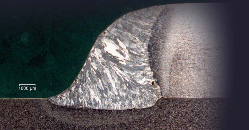
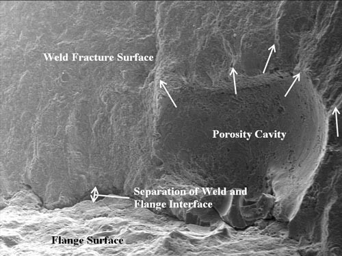
Welds may fail for a variety of reasons such as overload of the weldment or improper installation. In order to determine the root cause of a weld failure, individuals familiar with the various types of welding, testing, heat treatment, material requirements, and codes and standards should be consulted. Use of the wrong design code or standard can result in an improper design. Insufficient fusion at a weld joint can result in reduced load capacity. Improper welding techniques or applications may result in voids, cracks, or defects that can also reduce the load capacity of the weldment. Visual examination of a weld failure surface may not be sufficient to determine what happened. The use of specialized equipment, like a scanning electron microscope, may be needed to determine the cause of a failure. The complexity of weldment design and installation requires an experienced engineer to determine what happened and why.
Conclusion
Welds are all around us. A properly specified, designed, and tested weld is critical to ensuring the joined connection can withstand the forces and loads applied to the connection. Improper welding, heat treatment, or weld sizing can have catastrophic results. The next time you see a welded connection, you will be able to appreciate the complexity of the weld and how such a simple connection is part of a complex process.