Can I Put an LED Bulb in a Fluorescent Light Fixture?

Can I Put an LED Bulb in a Fluorescent Light Fixture?
Many people have energy savings on their minds these days. With the advent of LED tubes as a drop-in replacement for fluorescent tubes, the return on investment for LED conversion can be very appealing; the fluorescent fixture can be reused, with only some minor rewiring. However, the differences between the two technologies can result in unexpected side effects.
It is important to understand how fluorescent lighting works. A fluorescent tube cannot be connected directly to the electrical supply of a building. Instead, a device called a ballast must be placed between the tube and the electrical supply. There are different types of ballasts, but in general, their purpose is to limit the flow of current into the fluorescent tube.
LEDs are a different matter. Each LED tube or fixture is made up of many smaller LED elements, with circuitry that keeps the LED elements working together. There are three different types of LED tubes:
- UL Type A operates with the fluorescent ballast still in place;
- UL Type B operates directly off the electrical supply with no ballast; and
- UL Type C operates with an external LED driver.
LED tubes that fit into multiple categories, and the details of different types of ballasts, can complicate this picture. UL Type B tubes have an internal LED driver that performs many of the same functions that a ballast performs for fluorescent tubes, limiting the flow of current into the lighting elements. An LED driver approximates a fixed-power load on the electrical supply, like a computer power supply. That means that if the voltage to the tube decreases, the driver draws increased current to compensate. This gives UL Type B tubes the ability to operate on a wide range of voltages; LED tubes that fall in this category are often spec’d to operate between 120 volts and 277 volts.
While this sounds convenient, consider what would happen if there was a high-resistance connection between the fixture and the tube. High-resistance conditions can develop in almost any connection, and resistance in an electrical circuit translates into a voltage drop. When the tube draws current through the resistance, the voltage received by the tube drops. Since the LED driver in a UL Type B tube is a fixed-power load, it responds by pulling more current, and the increased current through the high-resistance connection causes the voltage received by the tube to drop even more. The product of the current drawn by the LED driver and the voltage drop in the connection is power lost as heat in the connection between the tube and the fixture. The more power is lost in the connection, the hotter the connection becomes.
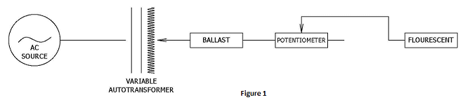
EDT conducted tests to determine how much heat might develop in such a connection. A standard, four-foot fluorescent tube light fixture was obtained from a local hardware store. Different combinations of fluorescent and LED tubes were connected to the fixture. A variable autotransformer was used as the electrical supply to vary the input voltage. A potentiometer (variable resistor) was inserted into the circuit upstream of the tube connection to simulate a high-resistance connection.
Different combinations of input voltage and connection resistance were tested with each fixture configuration:
- Using a fluorescent tube with a ballast (Figure 1), the power dissipated as heat in the connection was never more than 5.0 watts.
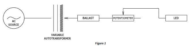
- Using a UL type A LED tube with a ballast the power dissipated as heat in the connection was never more than 2.6 watts.
- Using a UL type B LED tube connected directly to the electrical supply (Figure 3), the maximum power dissipated as heat in the connection was 57.4 watts.
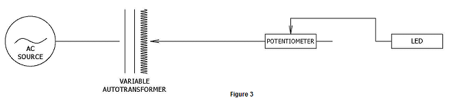
57.4 watts being dissipated into the plastic of the fixture connection would be enough to melt and ignite the plastic. Although the experimental tests described did not result in fire, EDT has consulted on at least one fire matching the described conditions.
The driver in the LED tubes tested appeared to operate in two modes. Under normal operation, the driver acted as a constant-power load. However, once the resistance increased past the point where the power lost in the resistance was greater than the power drawn by the LED driver, the driver instead operated in a manner more like a constant-current mode. In this mode, the driver pulled as much current as it was able without damaging itself, which resulted in a much greater voltage drop across the high-resistance connection, and a much lower voltage at the LED tube. Due to the lower input voltage to the LED tube, the LED driver was not able to draw its full rated power, but the LED tube continued putting out light a reduced level. This constant-current mode was where the highest power dissipations were observed. Fluorescent tubes, in general, have no such constant-current mode of operation, so the amount of heat that a fluorescent tube can dissipate into a high-resistance connection is more limited.
This result does not mean that UL Type B LED tubes are unsafe. But it does indicate that UL Type B LED tubes can introduce different hazards that do not exist with fluorescent tubes. Fluorescent fixtures that have been mechanically damaged or exposed to continuous vibration may have undetected high-resistance connections. Conversion of such a fixture to direct-connection LED tubes could result in a fire. Also, while the UL Type A LED tubes tested by EDT did not exhibit a constant-current mode of operation, this does not mean that all combinations of UL Type A LED tubes and ballasts will be similarly immune to the observed heating. UL Type C LED tubes were not tested by EDT; however, since a high-resistance connection between the tube and fixture would be on the load-side of a UL Type C driver, instead of on the line side, the response of the driver to a high-resistance connection would be expected to be more benign.
The management team of a facility that is considering the conversion of fixtures from fluorescent to LED tubes should take precautions. If the tube does not fit tightly between the sockets, such that the pin is exposed, then the fixture should be evaluated and potentially replaced. If a conversion has already been conducted, infrared surveys to identify unusual heating may be worthwhile. In addition, the use of UL Type C tubes, or of LED fixtures that doesn’t use tube connections, should be considered.
The behavior of LED drivers should be reconsidered from a design standpoint. In the testing described above, the connection resistance resulted in a reduced voltage to the LED tube, and it was only at very low tube voltages that excessive power loss was measured. An LED tube specified as operating between 120 and 277 volts was observed to continue operation at voltages as low as 20 volts; clearly, the LED driver tested was designed to continue operating, if at all possible. A driver designed to cease operating at some minimum threshold (88 volts, for example) would be less susceptible to the observed heating issues, while still operating in all useful conditions.
The energy savings from the use of LED lighting remain very appealing. Additional safety considerations during design and installation of LED options will allow the continued transition toward a safer and more energy-efficient world.